
Blower Door system in practice
Organisational rules before the start of acceptance testing
Point 5.1.3 of DIN EN 13829 leads to the time of measurement: “The measurement can take place only after the shell of the building to be inspected or part of the building is completed.” This means in practice that, among other things the interior and exterior plastering are completed and the front door is installed in the final state. Before starting the measurement, all outer openings are to be closed and, if necessary seal. Note: The actual checklist seal which components and which are not, is beyond the scope of this technical article. The interested layman can send an email to the author in this respect. All interior doors are opened, closed cabinets, fireplaces and heaters turned off, closed the outside air and exhaust air ducts with ball bubbles. During a tour in the building is to make sure that no persons are in the house which could provide a disturbance of the constant air conditions during the measurement.
Performing the measurement
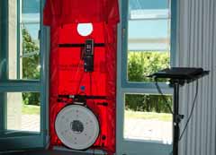
The photo above left shows the structure: In a building opening to the outside, preferably in a patio door, the frame and the sealing film is mounted. Into the round opening in the bottom third fan and the motor are mounted . At a cross-member , the control device for the air flow rates and for differential pressure measurement is attached . The system is operable to generate a normalized sub-pressure or excess-pressure in the building.
The air flow which flows in through the leaks in the building is measured. To determine the calculated value, the room volume is to be calculated. This task is for the measurement manager. Information from external planners may not be copied without verification. The air flow rate divided by the room volume gives the code. The Energy Saving Ordinance calls for building without air conditioning systems a guide value of n50 <3.0 h -1, for buildings with air conditioning systems a value of n50 <1.5 h -1. The measurement result and the boundary conditions are to be recorded.
The leakage test
During the acceptance test, the leakage test is performed. For this purpose, various test equipment is available. The instrument of choice is the anemometer. Thus, different flow velocities on the components to be determined, for example, on the windows, door frames, wall connectors, sockets, etc. For a quick visual inspection and the back of the hand is suitable. For targeted nebulization of critical points , the expert uses the “hand fogger” . Finally, the space can be committed with a thermal imaging camera. The most significant leakages are to be documented .
Even more efficient is the leakage location during construction. Here, leaks in the building envelope can still be fixed economically, for example, after the construction phase including installation of windows, but before plastering. The implementation of the blower door method during the construction period also sensitized the subsequent trades in the normal case. So the electrician is no longer mindlessly drill holes in the sealing layer.
For more information watch video part 1 und part 2
https://www.youtube.com/watch?v=67v_rTaZmOA quick guide 1
https://www.youtube.com/watch?v=x-RKcXwB8bQ quick guide 2